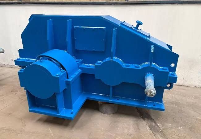
Industrial reducer manufacturing involves designing and producing mechanical power-transmission units that reduce rotational speed while increasing available torque.
Industrial reducers are used in conveyors, mixers, crushers, pumps, material-handling systems, production machinery, and many other applications.
A reducer must be engineered to handle the required torque, speed, load, operating cycle, temperature, and environmental conditions. Manufacturing therefore combines precision gear production, housing machining, bearing installation, lubrication systems, assembly, and performance testing.
What Is an Industrial Reducer?
An industrial reducer is a mechanical transmission device positioned between a power source and a driven machine. Its primary function is to reduce input rotational speed and provide a corresponding increase in output torque.
The reducer can contain one or more gear stages depending on the required speed ratio and application.
Main Functions
Industrial reducers can be used to:
- Reduce rotational speed
- Increase output torque
- Transfer mechanical power
- Control machine operating speed
- Adapt motor output to driven equipment
- Support controlled mechanical movement
Types of Industrial Reducers
Different gear arrangements provide different combinations of speed reduction, torque capacity, efficiency, size, and operating characteristics.
Helical Gear Reducers
Helical reducers use angled gear teeth that engage progressively. This design can provide smooth power transmission and is widely used in industrial machinery.
Typical applications include conveyors, mixers, packaging equipment, and general production machinery.
Bevel Gear Reducers
Bevel gear reducers are used when power transmission needs to change direction, often between shafts positioned at an angle.
They can be used in conveyors, material-handling systems, and machinery requiring specific drive orientations.
Worm Gear Reducers
Worm reducers consist of a worm and worm wheel. They can provide substantial speed reduction within a compact arrangement.
They are commonly considered for conveyors, lifting mechanisms, positioning systems, and selected industrial machines.
Planetary Gear Reducers
Planetary reducers use a sun gear, planet gears, and ring gear. Their compact architecture can provide high torque density and multiple reduction ratios.
They are used in applications such as robotics, heavy machinery, automation, and specialized power-transmission systems.
Helical-Bevel Reducers
These reducers combine helical and bevel gear stages. The configuration can provide efficient power transmission while allowing a change in shaft direction.
Parallel Shaft Reducers
Parallel shaft designs transmit power between parallel shafts and are frequently used where a compact arrangement and specific shaft configuration are required.
Main Components of an Industrial Reducer
The performance of a reducer depends on the interaction of several precision components.
Gears
Gears transmit rotational motion and torque between shafts. Their tooth profile, material, hardness, surface finish, and accuracy directly affect operating behavior.
Shafts
Shafts carry gears and transfer torque to and from the reducer. They must withstand torsional and bending loads generated during operation.
Bearings
Bearings support rotating shafts and maintain their alignment within the housing.
Housing
The housing contains the gears, shafts, bearings, and lubricant. It also provides structural support and protects internal components from contamination.
Seals
Seals help retain lubricant and limit the entry of dust, moisture, and other contaminants.
Lubrication System
Lubrication reduces friction and wear while helping manage heat generated during operation.
Industrial Reducer Manufacturing Process
Manufacturing typically involves several controlled stages.
1. Engineering and Design
The process begins with defining the required input speed, output speed, torque, ratio, load characteristics, duty cycle, mounting configuration, and environmental conditions.
Engineers then determine the appropriate gear arrangement, shaft dimensions, bearing configuration, housing design, and lubrication system.
2. Material Selection
Materials are selected according to the expected mechanical loads and operating environment.
Common materials include:
- Alloy steel
- Carbon steel
- Cast iron
- Ductile iron
- Aluminum alloys
- Engineering polymers for selected components
Gear materials often require specific heat-treatment processes to achieve the required surface and core properties.
3. Gear Blank Production
Gear blanks are prepared through processes such as forging, casting, cutting, and turning.
The selected method depends on the component size, material, production volume, and required mechanical properties.
4. Gear Tooth Machining
Gear teeth are generated using specialized machinery.
Common processes include:
- Gear hobbing
- Gear shaping
- Gear milling
- Gear grinding
- Gear shaving
- Gear honing
The selected process depends on gear geometry and required accuracy.
5. Heat Treatment
Heat treatment can improve gear hardness, wear resistance, fatigue performance, and dimensional stability.
Common processes include:
- Carburizing
- Nitriding
- Induction hardening
- Through hardening
- Tempering
The appropriate process depends on material grade, gear design, and operating requirements.
6. Shaft Manufacturing
Shafts are generally machined using turning, milling, grinding, keyway cutting, and other precision processes.
Critical shaft dimensions include bearing seats, gear locations, diameters, shoulders, and keyways.
7. Housing Manufacturing
Reducer housings may be produced through casting, fabrication, or machining.
Machining operations create precise bearing bores, mounting surfaces, inspection openings, and other critical features.
8. Gear Finishing
After heat treatment, precision gears may undergo grinding, honing, lapping, or other finishing processes.
Finishing can improve tooth geometry, surface characteristics, and engagement quality.
9. Assembly
Gears, shafts, bearings, seals, spacers, and other components are assembled according to engineering specifications.
Correct alignment and controlled assembly procedures are essential for reliable operation.
10. Testing
Completed reducers undergo inspection and performance testing according to the manufacturer's quality procedures and applicable requirements.
Gear Manufacturing Equipment Used in Reducer Production
Specialized machinery is required to produce accurate reducer components.
| Manufacturing Stage | Typical Equipment | Purpose |
|---|---|---|
| Blank preparation | CNC lathe | Gear and shaft blank machining |
| Tooth generation | Gear hobbing machine | Gear tooth production |
| Gear shaping | Gear shaping machine | Internal or external gear production |
| Finishing | Gear grinding machine | Precision tooth finishing |
| Shaft machining | CNC turning center | Shaft geometry |
| Housing machining | CNC machining center | Bearing bores and mounting surfaces |
| Heat treatment | Heat-treatment furnace | Material property modification |
| Inspection | Gear measuring equipment | Tooth and dimensional verification |
| Assembly | Precision assembly equipment | Final reducer construction |
Gear Ratio in Industrial Reducers
The gear ratio determines the relationship between input and output speed.
For a simple gear pair, the relationship can be expressed as:
Gear Ratio = Input Speed ÷ Output Speed
For example, if a motor operates at 1,500 revolutions per minute and the reducer provides an output speed of 150 revolutions per minute, the approximate reduction ratio is 10:1.
Actual reducer performance depends on the complete gear arrangement, load, efficiency, and operating conditions.
Torque and Power Considerations
Reducing rotational speed generally increases available output torque, subject to power losses and mechanical efficiency.
Engineers should consider:
- Input power
- Input speed
- Output speed
- Required output torque
- Starting torque
- Peak loads
- Shock loads
- Duty cycle
- Service factor
Selecting a reducer based only on nominal motor power may be insufficient for applications involving frequent starts, stops, impacts, or varying loads.
Applications of Industrial Reducers
Industrial reducers are used across a wide range of industries.
Conveyor Systems
Reducers control conveyor speed and provide the torque required to move bulk or packaged materials.
Mining Equipment
Heavy-duty reducers are used in conveyors, crushers, feeders, mills, and other mining equipment where high loads and demanding operating environments are common.
Material Handling
Cranes, hoists, elevators, and other material-handling systems use reducers to control mechanical movement.
Manufacturing Machinery
Production equipment such as mixers, extruders, packaging machines, and processing systems can incorporate gear reducers.
Cement and Construction Equipment
Reducers are used in mixers, conveyors, crushers, and other machinery used in construction-material processing.
Food Processing Equipment
Mixers, conveyors, filling equipment, and processing machinery may use appropriately configured reducers.
Renewable Energy Systems
Specialized gear systems are used in certain renewable-energy equipment to transmit and control mechanical power.
Industrial Reducer Testing
Testing helps verify that a completed reducer performs according to its design requirements.
No-Load Testing
The reducer may be operated without the full working load to evaluate noise, vibration, temperature, lubrication, and general operation.
Load Testing
Controlled loads can be applied to assess torque transmission, temperature behavior, efficiency, and mechanical performance.
Noise and Vibration Testing
Abnormal noise or vibration may indicate gear misalignment, bearing problems, excessive backlash, or other mechanical issues.
Leakage Testing
Housing and seal conditions can be evaluated to identify potential lubricant leakage.
Dimensional Inspection
Critical gear, shaft, housing, and mounting dimensions should be verified before final assembly.
Factors Affecting Reducer Performance
Gear Accuracy
Accurate tooth geometry supports proper gear engagement and helps control noise, vibration, and wear.
Lubrication
Insufficient or inappropriate lubrication can increase friction and accelerate component degradation.
Alignment
Correct alignment of gears, shafts, and bearings is essential for balanced load distribution.
Operating Temperature
Excessive temperature can affect lubricant performance and component life.
Load Conditions
Repeated shock loads or loads above the rated operating range can place additional stress on gears, shafts, and bearings.
Contamination
Dust, water, metal particles, and other contaminants can affect lubricant quality and damage internal components.
How to Select an Industrial Reducer
Choosing an industrial reducer requires a complete understanding of the driven machine.
Determine Input Speed
Identify the motor or prime mover's operating speed.
Determine Required Output Speed
Establish the target speed for the driven equipment.
Calculate Required Ratio
The required reduction ratio can then be determined from the input and desired output speeds.
Evaluate Output Torque
Calculate the continuous and peak torque requirements, including starting and shock loads.
Consider Duty Cycle
Continuous, intermittent, reversing, and high-frequency operating cycles can impose different mechanical demands.
Select the Gear Configuration
Choose between helical, bevel, worm, planetary, parallel-shaft, or combined configurations based on the application.
Evaluate Mounting Requirements
Check shaft orientation, mounting position, flange requirements, base dimensions, and available installation space.
Consider Environmental Conditions
Temperature, dust, moisture, chemicals, outdoor exposure, and washdown requirements can influence housing, seals, lubrication, and material selection.
Maintenance of Industrial Reducers
Regular maintenance helps maintain reliable operation.
Important maintenance activities include:
- Checking lubricant condition
- Maintaining appropriate lubricant levels
- Inspecting seals
- Monitoring operating temperature
- Checking abnormal vibration
- Monitoring unusual noise
- Inspecting mounting bolts
- Checking shaft alignment
- Inspecting gear condition
Condition monitoring can also use vibration analysis, temperature monitoring, oil analysis, and other diagnostic methods to identify developing issues.
Frequently Asked Questions
What is industrial reducer manufacturing?
Industrial reducer manufacturing is the process of designing and producing mechanical gear-reduction units used to decrease rotational speed and transmit higher output torque to industrial machinery.
What types of industrial reducers are available?
Common types include helical, bevel, worm, planetary, helical-bevel, and parallel-shaft reducers. The appropriate configuration depends on speed, torque, shaft arrangement, and application requirements.
Which materials are used to manufacture industrial reducers?
Common materials include alloy steel, carbon steel, cast iron, ductile iron, aluminum alloys, and selected engineering polymers. Material selection depends on the component and operating conditions.
Why is heat treatment used in reducer manufacturing?
Heat treatment can improve hardness, wear resistance, fatigue performance, and other mechanical properties of suitable gear materials.
How do I select an industrial gear reducer?
Consider input speed, output speed, reduction ratio, required torque, power, duty cycle, shock loads, mounting arrangement, environmental conditions, gear configuration, lubrication, and dimensional requirements.
Conclusion
Industrial reducer manufacturing combines precision engineering, gear production, heat treatment, machining, assembly, and testing to create reliable mechanical power-transmission equipment. Helical, bevel, worm, planetary, and other reducer configurations can be designed for different combinations of speed reduction, torque, shaft orientation, and operating conditions.
A suitable reducer should be selected according to the complete application rather than motor power alone. Input and output speed, torque, duty cycle, load characteristics, environment, mounting arrangement, lubrication, and gear configuration all influence the final design.